Wednesday, February 28, 2007

High frequency resistance welding (HFRW)

High frequency resistance welding (HFRW) is a resistance welding process which produces coalescence of metals with the heat generated from the resistance of the work pieces to a high-frequency alternating current in the 10,000 to 500,000 hertz range and the rapid application of an upsetting force after heating is substantially completed. The path of the current in the work piece is controlled by the proximity effect.
This process is ideally suited for making pipe, tubing, and structural shapes. It is used for other manufactured items made from continuous strips of material. In this process the high frequency welding current is introduced into the metal at the surfaces to be welded but prior to their contact with each other.
Current is introduced by means of sliding contacts at the edge of the joint. The high-frequency welding current flows along one edge of the seam to the welding point between the pressure rolls and back along the opposite edge to the other sliding contact.
The current is of such high frequency that it flows along the metal surface to a depth of several thousandths of an inch. Each edge of the joint is the conductor of the current and the heating is concentrated on the surface of these edges. At the area between the closing rolls the material is at the plastic temperature, and with the pressure applied, coalescence occurs.

......Read More......

Percussion welding (PEW)

Percussion welding (PEW) is a resistance welding process which produces coalescence of the abutting members using heat from an arc produced by a rapid discharge of electrical energy.
Pressure is applied progressively during or immediately following the electrical discharge. This process is quite similar to flash welding and upset welding, but is limited to parts of the same geometry and cross section. It is more complex than the other two processes in that heat is obtained from an arc produced at the abutting surfaces by the very rapid discharge of stored electrical energy across a rapidly decreasing air gap. This is immediately followed by application of pressure to provide an impact bringing the two parts together in a progressive percussive manner. The advantage of the process is that there is an extremely shallow depth of heating and time cycle is very short. It is used only for parts with fairly small cross-sectional areas.

......Read More......

Upset welding (UW)

Upset welding (UW) is a resistance welding process which produces coalescence simultaneously over the entire area of abutting surfaces or progressively along a joint, by the heat obtained from resistance to electric current through the area where those surfaces are in contact.
Pressure is applied before heating is started and is maintained throughout the heating period. The equipment used for upset welding is very similar to that used for flash welding. It can be used only if the parts to be welded are equal in cross-sectional area. The abutting surfaces must be very carefully prepared to provide for proper heating.
The difference from flash welding is that the parts are clamped in the welding machine and force is applied bringing them tightly together. High-amperage current is then passed through the joint, which heats the abutting surfaces. When they have been heated to a suitable forging temperature an upsetting force is applied and the current is stopped. The high temperature of the work at the abutting surfaces plus the high pressure causes coalescence to take place. After cooling, the force is released and the weld is completed.

......Read More......

Flash Welding (FW)

Flash Welding (FW) is a resistance welding process which produces coalescence simultaneously over the entire area of abutting surfaces, by the heat obtained from resistance to electric current between the two surfaces, and by the application of pressure after heating is substantially completed.
Flashing and upsetting are accompanied by expulsion of metal from the joint. During the welding operation there is an intense flashing arc and heating of the metal on the surface abutting each other. After a predetermined time the two pieces are forced together and coalescence occurs at the interface, current flow is possible because of the light contact between the two parts being flash welded.
The heat is generated by the flashing and is localized in the area between the two parts. The surfaces are brought to the melting point and expelled through the abutting area. As soon as this material is flashed away another small arc is formed which continues until the entire abutting surfaces are at the melting temperature. Pressure is then applied and the arcs are extinguished and upsetting occurs.

......Read More......

Resistance seam welding (RSEW)

Resistance seam welding (RSEW) is a resistance welding process which produces coalescence at the faying surfaces the heat obtained from resistance to electric current through the work parts held together under pressure by electrodes.
The resulting weld is a series of overlapping resistance spot welds made progressively along a joint rotating the electrodes. When the spots are not overlapped enough to produce gaslight welds it is a variation known as roll resistance spot welding. This process differs from spot welding since the electrodes are wheels. Both the upper and lower electrode wheels are powered. Pressure is applied in the same manner as a press type welder. The wheels can be either in line with the throat of the machine or transverse. If they are in line it is normally called a longitudinal seam welding machine. Welding current is transferred through the bearing of the roller electrode wheels. Water cooling is not provided internally and therefore the weld area is flooded with cooling water to keep the electrode wheels cool.
In seam welding a rather complex control system is required. This involves the travel speed as well as the sequence of current flow to provide for overlapping welds. The welding speed, the spots per inch, and the timing schedule are dependent on each other. Welding schedules provide the pressure, the current, the speed, and the size of the electrode wheels.
This process is quite common for making flange welds, for making watertight joints for tanks, etc. Another variation is the so-called mash seam welding where the lap is fairly narrow and the electrode wheel is at least twice as wide as used for standard seam welding. The pressure is increased to approximately 300 times normal pressure. The final weld mash seam thickness is only 25% greater than the original single sheet.

......Read More......

Projection welding (RPW)

Projection welding (RPW) is a resistance welding process which produces coalescence of metals with the heat obtained from resistance to electrical current through the work parts held together under pressure by electrodes.
The resulting welds are localized at predetermined points by projections, embossments, or intersections. Localization of heating is obtained by a projection or embossment on one or both of the parts being welded. There are several types of projections: (1) the button or dome type, usually round, (2) elongated projections, (3) ring projections, (4) shoulder projections, (5) cross wire welding, and (6) radius projection.
The major advantage of projection welding is that electrode life is increased because larger contact surfaces are used. A very common use of projection welding is the use of special nuts that have projections on the portion of the part to be welded to the assembly.

......Read More......

Resistance spot welding

Resistance spot welding (RSW) is a resistance welding process which produces coalescence at the faying surfaces in one spot by the heat obtained from resistance to electric current through the work parts held together under pressure by electrodes.
The size and shape of the individually formed welds are limited primarily by the size and contour of the electrodes. The equipment for resistance spot welding can be relatively simple and inexpensive up through extremely large multiple spot welding machines. The stationary single spot welding machines are of two general types: the horn or rocker arm type and the press type.
The horn type machines have a pivoted or rocking upper electrode arm, which is actuated by pneumatic power or by the operator`s physical power. They can be used for a wide range of work but are restricted to 50 kVA and are used for thinner gauges. For larger machines normally over 50 kVA, the press type machine is used. In these machines, the upper electrode moves in a slide. The pressure and motion are provided on the upper electrode by hydraulic or pneumatic pressure, or are motor operated.
For high-volume production work, such as in the automotive industry, multiple spot welding machines are used. These are in the form of a press on which individual guns carrying electrode tips are mounted. Welds are made in a sequential order so that all electrodes are not carrying current at the same time.

......Read More......

Resistance Welding

Resistance welding is a group of welding processes in which coalescence is produced by the heat obtained from resistance of the work piece to electric current in a circuit of which the work piece is a part and by the application of pressure. There are at least seven important resistance-welding processes. These are flash welding, high-frequency resistance welding, percussion welding, projection welding, resistance seam welding, resistance spot welding, and upset welding. They are alike in many respects but are sufficiently different.
Resistance Welding classified as follows :
  • Resistance spot welding (RSW)
  • Projection welding (RPW)
  • Resistance seam welding (RSEW)
  • Flash Welding (FW)
  • Upset welding (UW)
  • Percussion welding (PEW)
  • High frequency resistance welding (HFRW)

......Read More......

Tuesday, February 27, 2007

Robotic Welding (Part 2)

There are two popular types of industrial welding robots. The two are articulating robots and rectilinear robots. Robotics control the movement of a rotating wrist in space. A description of some of these welding robots are described below:

Rectilinear robots move in line in any of three axes (X, Y, Z). In addition to linear movement of the robot along axes there is a wrist attached to the robot to allow rotational movement. This creates a robotic working zone that is box shaped.

Articulating robots employ arms and rotating joints. These robots move like a human arm with a rotating wrist at the end. This creates an irregularly shaped robotic working zone.

There are many factors that need to be considered when setting up a robotic welding facility. Robotic welding needs to be engineered differently than manual welding. Some of the consideration for a robotic welding facility are listed below:

  • Accuracy and repeatability
  • Number of axes
  • Reliability
  • Fixtures
  • Programming
  • Seam tracking systems
  • Maintenance
  • Controls
  • Weld monitors
  • Arc welding equipment
  • Positioners
  • Part transfer
A robotic welding system may perform more repeat ably than a manual welder because of the monotony of the task. However, robots may necessitate regular recalibration or reprogramming.

Robots should have the number of axes necessary to permit the proper range of motion. The robot arm should be able to approach the work from multiple angles.

Robotic welding systems are able to operate continuously, provided appropriate maintenance procedures are adhered to. Continuous production line interruptions can be minimized with proper robotic system design. Planning for the following contingencies needs to be completed:

  • Rapid substitution of the inoperable robots.
  • Installing backup robots in the production line
  • Redistributing the welding of broken robots to functioning robots close by
(AMC-Weldingengineer.com)

......Read More......

Robot welding


When should robots be used for welding?

A welding process that contains repetitive tasks on similar pieces might be suitable for automation. The number of items of any type to be welded determines whether automating a process or not. If parts normally need adjustment to fit together correctly, or if joints to be welded are too wide or in different positions from piece to piece, automating the procedure will be difficult or impossible. Robots work well for repetitive tasks or similar pieces that involve welds in more than one axis or where access to the pieces is difficult.

Why robot welding?

The most prominent advantages of automated welding are precision and productivity. Robot welding improves weld repeatability. Once programmed correctly, robots will give precisely the same welds every time on workpieces of the same dimensions and specifications.

Automating the torch motions decreases the error potential which means decreased scrap and rework. With robot welding you can also get an increased output. Not only does a robot work faster, the fact that a fully equipped and optimized robot cell can run for 24 hours a day, 365 days a year without breaks makes it more efficient than a manual weld cell.

Another benefit of automated welding is the reduced labor costs. Robotic welding also reduces risk by moving the human welder/operator away from hazardous fumes and molten metal close to the welding arc.

What welding processes are suitable for robot welding?

Most production welding processes can be used in automated applications. The most popular, used in perhaps 80 percent of applications, is the solid wire GMAW process. This process is best for most high production situations because no postweld cleanup is required.


(Robot-welding.com)

......Read More......

Plasma Arc Welding

In plasma arc welding, a shielded arc is struck between a non consumable electrode and the torch body, and this arc transforms an inert gas into plasma. A plasma is a gas which is heated to an extremely high temperature and ionized so that it becomes electrically conductive. Similar to GTAW (TIG), the plasma arc welding process uses this plasma to transfer an electric arc to a work piece. The metal to be welded is melted by the intense heat of the arc and fuses together. In the plasma welding torch a tungsten electrode is located within a copper nozzle having a small opening at the tip. A pilot arc is initiated between the torch electrode and nozzle tip. This arc is then transferred to the metal to be welded. Shielding gas is obtained from the hot ionized gas issuing from the orifice. Auxiliary inert shielding gas or a mixture of inert gases is normally used.

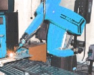
By forcing the plasma gas and arc through a constricted orifice, the torch delivers a high concentration of heat to a small area. With high performance welding equipment, the plasma process produces exceptionally high quality welds. Like gas tungsten arc welding, the plasma arc welding process can be used to weld most commercial metals, and it can be used for a wide variety of metal thicknesses.

(Robot Welding dot com)

......Read More......

Submerged Arc Welding (SAW)


Submerged arc welding (SAW) is an arc welding process that fuses together the parts to be welded by heating them with one or more electric arcs between one or more bare electrodes and the work piece. The submerged arc welding process utilizes the heat of an arc between a continuously fed electrode and the work. The heat of the arc melts the surface of the base metal and the end of the electrode. The metal melted off the electrode is transferred through the arc to the workpiece, where it becomes the deposited weld metal.

Shielding is obtained from a blanket of granular flux, which is laid directly over the weld area. The flux close to the arc melts and intermixes with the molten weld metal and helps purify and fortify it. The flux forms a glasslike slag that is lighter in weight than the deposited weld metal and floats on the surface as a protective cover. The weld is submerged under this layer of flux and slag- hence the name submerged arc welding. (Robot Welding dot com)

......Read More......

Shielded Metal Arc Welding (SMAW) or Stick Welding


Shielded Metal Arc Welding (SMAW) is frequently referred to as stick or covered electrode welding. Stick welding is among the most widely used welding processes.

The flux covering the electrode melts during welding. This forms the gas and slag to shield the arc and molten weld pool. The slag must be chipped off the weld bead after welding. The flux also provides a method of adding scavengers, deoxidizers, and alloying elements to the weld metal.

Stick Weld - SMAW

Stick Welding Benefits

  • Equipment used is simple, inexpensive, and portable
  • Electrode provides and regulates its own flux
  • Lower sensitivity to wind and drafts than gas shielded welding processes
  • All position capability

Common Stick Welding Concerns

We can help optimize your welding process variables. Evaluate your current welding parameters and techniques. Help eliminate common welding problems and discontinuities such as those listed below:

Weld Discontinuities

  • Undercut
  • Incomplete fusion
  • Porosity
  • Slag Inclusions
  • Cracks

Stick Welding Problems


  • Arc Blow
  • Arc Stability
  • Excessive spatter
  • Incorrect weld profile
  • Rough surface
  • Porosity
(AMC- Welding Engineer Site)

......Read More......

Flux Core Arc Welding (FCAW) Advantages & Disadvantages

by Marty Rice

Marty Rice is a welding instructor at a high school career center in Texas. He is the author of Arc Welding 101, which appears in each issue of Practical Welding Today®, and is an honorary member of the Iron Workers Local 263.


Advantages
When using FCAW, a welder does not have to stop and change rods as in SMAW. That means longer beads with fewer restarts, high weld deposit, and more production. This means less chance of defects in the restart area.
The process uses DCEP and produces deep fusion with a good weld appearance. In addition, smaller-diameter wires can be used in all positions.
FCAW can be used with or without shielding gas; if you use shielding gas, carbon dioxide is very cheap. (Other gases, such as 75/25, also can be used.) The flux contains oxidizers, so the base metal needs minimum cleaning before a weld is made. Postweld cleanup is a breeze because the slag chips off very easily.
On top of that, the wire stickout with FCAW is a lot longer than with GMAW (about ½ to ¾ inch), so welders can see and control the puddle much better. It couldn't be any better if it welded itself--which it can if it is set up for automatic welding. I usually can have a student welding satisfactorily the first day with FCAW (and GMAW, for that matter).

Disadvantages
Fumes! FCAW puts out more smoke than a Houston barbecue joint. If you are using FCAW in a shop, you really should have a strong point-of-contact ventilation system. If not, your lungs are going to be full of welding fumes, and that just isn't healthy.
Other than the fumes, the only other disadvantage is that FCAW usually is used only on mild steel. It has limited uses for cast iron and stainless, but mild steel is all I've ever seen it used on.
In the Field
The only time I used FCAW in the field was on column splices in which one column was stacked on the one below it. This arrangement uses gusset plates where the bolts are attached, and the column itself is beveled for a groove weld.
The included angle (the sum of both column angles where the beveled edges meet) usually is very wide, which leaves a large amount of welding to be done. These are zero-defect welds that are X-rayed for soundness. Stick welding takes entirely too long for these angles and requires too many restarts, which increase the chance of defects.
With FCAW, one welder sits in a basket on one side of the column while another welds the opposite side. This puts the same amount of heat on each side, eliminating any distortion. It makes for good, continuous beads with little time lost. And in construction, time equals money.

......Read More......

Flux Core Arc Welding (FCAW) Overview

by : Marty Rice
FCAW not only is easy to teach and to use, it's one of the most flexible welding processes around.
Any welder who has been in the trade very long has a lot of interesting tales to tell, and I've got quite a few myself.

I started out in an oil and agriculture equipment repair shop. We repaired and rebuilt bulldozers, road graders, dirt movers, and the like. I was the maintenance-repair welder, and I mainly used 7018 and 6011 stick welding. (By the way, another name for "maintenance-repair welder" is "Hey you, come fix this now!")

I learned a lot on that job. The scariest project I had there was working overtime all by myself. The place was a few miles outside the city on about 100 acres. I wasn't afraid of the bogeyman or robbers, but I met my fear one night when I decided to start a big D9 bulldozer before I left for home. I just had to hear that big piece of machinery fired up.
This 'dozer was so huge it took up a whole section of the shop and needed a starter motor just to get the engine going. I got it started all right, but once I did, I didn't know how to shut it off! Man, I was freaking out trying to shut that dang thing down, afraid that if I pulled the wrong lever, I'd go flying through the wall. I finally shut it down—after taking a couple of years off my life from all the stress.

The worst part of that job was washing cow manure off bulldozers in a -40-degree wind chill so I could weld or cut on defects. Being the new guy, I always ended up with the high-pressure hose out on the back 40. But that was just part of the job, and doing it made me a better man.
After a year there I took a job in a black-iron fabrication plant. We fabricated and welded structural members (beams, columns, and braces) for the construction industry and worked on plant maintenance and modifications.

After passing a 7018 plate test, I was asked if I could use the flux-core process.
"Of course I can!" I said as I remembered my former welding teachers Phil Newell and Mike Waldrop screaming in my ear to "relax my hand and watch the puddle." Phil once said that if I did those things, along with the other basics, there was no process I couldn't do.
I had a lot to learn, though. Confidence is great as long as it doesn't turn into cockiness. I learned early on to ask questions if I didn't know something and to try to learn all the tricks and tips I could from the old-timers.
I also learned that being in the welding field a long time doesn't guarantee good craftsmanship. There are a few people out there who always have been and always will be slackers, but they usually don't last long on a job. Luckily, most of the old hands in the welding trade are good craftsmen. A welder new to the trade can learn a great deal from them.
When I started in the black-iron shop, my partner was a crusty old World War II veteran. That guy could cuss, gripe, and complain for hours on end, but he was a wealth of information. Under that attitude was a really nice guy who enjoyed teaching me.
We used flux-cored arc welding (FCAW) on just about everything in there. FCAW is an excellent process, whether you are a hobbyist or a skilled structural welder in the shop or field. It is a very efficient process to use in all conditions.
FCAW is very similar to gas metal arc welding (GMAW). In GMAW, a solid steel wire is fed from a spool through drive rolls that push, pull, or push and pull the wire through the gun. The same is true with FCAW.

GMAW uses direct current, electrode positive (DCEP), while FCAW uses direct current, electrode negative (DCEN), or direct current electrode positive (DCEP).
GMAW uses a shielding gas to protect the puddle from contaminants in the atmosphere such as nitrogen and hydrogen. On the other hand, FCAW uses a tubular wire that has flux in the middle. The flux then burns, emitting a shielding gas, which protects the puddle. The flux turns into slag, just as in the shielded metal arc welding (SMAW) process. Shielding gas is not necessary, but it can be used to make a bead even smoother.
Marty Rice is a welding instructor at a high school career center in Texas. He is the author of Arc Welding 101, which appears in each issue of Practical Welding Today®, and is an honorary member of the Iron Workers Local 263.

......Read More......

Common Problems and Remedies for GMAW (Part 2)

Improper Bead Problem #2: TechniqueA concave or convex-shaped bead may also be caused by using an improper welding technique. For example, a push or forehand technique tends to create a flatter bead shape than a pull or backhand technique.RemedyFor best bead shapes, it is recommended to use a push angle of 5-10 degrees.
Improper Bead Problem #3: Inadequate Work CableProblems with the work cable can result in inadequate voltage available at the arc. Evidence of a work cable problem would be improper bead shape or a hot work cable.
RemedyWork cables have a tendency to overheat if they are too small or excessively worn. In replacing the cable, consult a chart to determine size based on length and current being used. The higher the current and longer the distance, the larger the cable needed.
III. Lack of FusionIf the consumable has improperly adhered to the base metal, a lack of fusion may occur. Improper fusion creates a weak, low quality weld and may ultimately lead to structural problems in the finished product.
Lack of Fusion Problem: Cold Lapping in the Short Arc Transfer ProcessIn short arc transfer, the wire directly touches the weld pool and a short circuit in the system causes the end of the wire to melt and detach a droplet. This shorting happens 40 to 200 times per second. Fusion problems may occur when the metal in the weld pool is melted, but there is not enough energy left to fuse it to the base plate. In these cases, the weld will have a good appearance, but none of the metal has actually been joined together. Since lack of fusion is difficult to detect visually, it must be checked by dye-penetrant, ultrasonic or bend testing.
Remedies:To guarantee correct fusion, ensure that voltage and amperage are set correctly. If the operator is still having problems after making those adjustments, it may require a change in the welding technique. For example, changing to a flux-cored wire or using the spray arc transfer method instead. In spray arc transfer, the arc never goes out so cold lapping and lack of fusion are not issues. Spray arc welding takes place at amperages high enough to melt the end of the wire and propel the droplet across the arc into the weld puddle.
IV. Faulty Wire DeliveryIf the wire is not feeding smoothly or if the operator is experiencing a chattering sound within the gun cable, there may be a problem with the wire delivery system. Most of the problems related to wire delivery are attributed to equipment set-up and maintenance.
Faulty Wire Delivery Problem #1: Contact Tip There is a tendency among operators to use oversized tips, which can lead to contact problems, inconsistencies in the arc, porosity and poor bead shape.
Remedies:First, make sure that the contact tip in the gun is in working order and sized appropriately to the wire being used. Visually inspect the tip and if it is wearing out (becoming egg-shaped), it will need to be replaced.
Faulty Wire Delivery Problem #2: Gun Liner A gun liner, like the contact tip, must be sized to the wire being fed through it. It also needs to be cleaned or replaced when wire is not being fed smoothly.
Remedy:To clean the liner, blow it out with low-pressure compressed air from the contact tip end, or replace the liner.
Faulty Wire Delivery Problem #3: Worn Out GunInside the gun are very fine strands of copper wire that will eventually break and wear out with time. Remedy:If the gun becomes extremely hot during use in one particular area, that is an indication that there is internal damage and it will need to be replaced. In addition, be certain that the gun is large enough for the application. Operators like to use small guns since they are easy on the hand, but if the gun is too small for the application, it will overheat.
Faulty Wire Delivery Problem #4: Drive Roll Drive rolls on the wire feeder periodically wear out and need to be replaced. Remedies:There are usually visual indications of wear on the grooves of the rolls if replacement is necessary. Also, make sure that the drive roll tension is set properly. To check tension, disconnect the welding input cable from the feeder or switch to the cold feed option. Feed the wire and pinch it as it exits the gun with the thumb and forefinger. If the wire can be stopped by pinching, more drive roll tension is needed.
The optimum tension will be indicated by feeding that is not stopped while pinching the wire. If the drive roll tension is too high, it may deform the wire leading to birdnesting (tangling) and a burn back (when the arc climbs the wire and fuses the wire to the contact tip.) Make sure that the drive rolls and the guide tube are as close together as possible. Next, check the path from where the wire leaves the reel to where it enters the drive rolls. The wire must line up with the incoming guide tubes so there is no scrapping of the wire as it goes through the tube. On some wire feeders, the wire spool position is adjustable -- align it so that it makes a straight path into the tube.
Faulty Wire Delivery Problem #5: Wire Coming Off Reel and TanglingSome wire feeding problems occur because the inertia from the wire reel causes it to coast after the gun trigger is released.Remedy:If the reel continues to coast, the wire on the reel will loosen and the wire may come off or become tangled. Most wire feeding systems have an adjustable brake on the wire reel. The brake tension should be set so that the reel does not coast. By following these four guidelines, a GMAW operator new to the world of welding or even someone more experienced should have an easier time diagnosing problems before they affect the quality of the work.
Source : Lincoln Electric Company

......Read More......

Common Problems and Remedies for GMAW (Part 1)


In much the same way that the automatic transmission has simplified the process of driving, Gas Metal Arc Welding (GMAW) has simplified the process of welding. Of all welding methods, GMAW is said to be one of the easiest to learn and perform. The main reason is because the power source does virtually all the work as it adjusts welding parameters to handle differing conditions; much like the sophisticated electronics of an automatic transmission.Because less skill is required, many operators are able to GMA weld at an acceptable level with limited training. These same operators run into trouble, however, when they begin creating inferior welds and are unable to diagnose and correct their own problems.


The guidelines listed below will help even inexperienced operators create high quality welds as well as offering tips for those who have been using the GMAW process for a number of years. Most common welding problems fall into four categories:

I. Weld porosity, II. Improper weld bead profile, III. Lack of fusion, and IV. Faulty wire delivery related to equipment set-up and maintenance.


I. Weld Metal PorosityPorosity

Problem #1: Improper Surface ConditionsThe most common cause of weld porosity is an improper surface condition of the metal. For example, oil, rust, paint or grease on the base metal may prevent proper weld penetration and hence lead to porosity. Welding processes that generate a slag such as Shielded Metal Arc Welding (SMAW) or Flux-Cored Arc Welding (FCAW) tend to tolerate surface contaminates better than GMAW since components found within the slag help to clean the metal’s surface. In GMAW, the only contamination protection is provided by the elements which are alloyed into the wire.


RemediesTo control porosity, use a deoxidizer within the wire such as silicon, manganese or trace amounts of aluminum, zirconium or titanium. Wire chemistry can be determined by referring to the American Welding Society (AWS) wire classification system. Test the various types of wire available to find the right chemistry for a given application. To start, try the most common wire type, ER70S-3 (Lincoln L50) which contains 0.9-1.4 percent manganese and 0.45-0.75 percent silicon. If porosity is still present in the finished weld, increase the amount of silicon and manganese found in the wire by switching to an ER70S-4 (Lincoln L54) or an ER70S-6 which has the highest levels of silicon (0.8 -1.15 percent) and manganese (1.4-1.8 percent). Some operators prefer to use a triple deoxidizer such as ER70S-2 (Lincoln L52) which contains aluminum, zirconium or titanium in addition to the silicon and manganese.In addition to changing the wire, further prevent porosity by cleaning the surface of the metal with a grinder or chemical solvents (such as a degreaser.) A word of caution though if using solvents, be certain not to use a chlorinated degreaser such as trichlorethylene near the welding arc -- the fume may react with the arc and produce toxic gases.


Porosity Problem #2: Gas Coverage The second leading cause of porosity in welds is a problem with the shielding gas coverage. The GMAW process relies on the shielding gas to physically protect the weld puddle from the air and to act as an arc stabilizer. If the shielding gas is disturbed, there is a potential that air could contaminate the weld puddle and lead to porosity.Remedies Shielding gas flow varies depending on wire size, amperage, transfer mode and wind speed. Typical gas flow should be approximately 30-40 cubic feet per hour. Using a flow meter, check that the shielding gas flow is set properly. There are a variety of flow meters on the market today ranging from simple dial gauges to ball flows all the way up to sophisticated, computerized models. Some operators mistakenly think that a pressure regulator is all that is needed, but the pressure meter will not set flow. A pure carbon dioxide shielding gas requires the use of special flow meters designed specifically for carbon dioxide. These special flow meters are not affected by the frosting that may occur as the carbon dioxide changes from liquid form to a gas.If high winds are blowing the shielding gas away from the puddle, it may be necessary to erect wind screens. According to the AWS Structural Welding Code, it is advisable not to GMA weld when wind speeds are greater than 5 mph. Indoors, ventilation systems may hamper gas coverage. In this case, redirect air flow away from the puddle. If fume extraction is necessary, use equipment designed specifically for this purpose such as MAGNUM™ Extraction Guns from Lincoln Electric -- they will remove the fume, but not disturb the shielding gas.A turbulent flow of gas as it exits the gun may also lead to porosity problems. Ideally, the gas will lay over the weld puddle much like a blanket. Turbulent gas flow can be caused by too high a flow, an excessive amount of spatter inside the gun nozzle, or spatter build-up in the gas diffuser. Other possible causes of insufficient gas flow may be damaged guns, cables, gas lines, hoses or loose gas fittings. These damaged accessories may create what is referred to as a “venturi effect” where air is sucked in through these openings and flow is reduced.Lastly, welding with a drag or backhand technique can lead to gas coverage problems. Try to weld with a push or forehand technique which lays the gas blanket out ahead of the arc and lets the gas settle into the joint. Porosity Problem#3: Base Metal PropertiesAnother cause of weld porosity may be attributed simply to the chemistry of the base metal. For instance, the base metal may be extremely high in sulfur content. Remedy Unfortunately, if the problem with porosity lies within the base metal properties, there is not much that can be done. The best solution is to use a different grade of steel or switch to a slag-generating welding process.II. Improper Weld Bead ProfileIf operators are experiencing a convex-shaped or concave-shaped bead, this may indicate a problem with heat input or technique. Improper Bead Problem #1: Insufficient Heat InputA convex or “ropy” bead indicates that the settings being used are too cold for the thickness of the material being welded. In other words, there is insufficient heat in the weld to enable it to penetrate into the base metal.


Remedies
To correct a problem with running “too cold,” an operator must first determine if the amperage is proper for the thickness of the material. Charts are available from the major manufacturers, including Lincoln Electric, that provide guidelines on amperage use under varying conditions. If the amperage is determined to be high enough, check the voltage. Voltage that is too low usually is accompanied by another telltale sign of a problem: a high amount of spatter. On the other hand, if voltage is too high, the operator will have problems controlling the process and the weld will have a tendency to undercut. One way to check if the voltage is set properly is to test it by listening. A properly running arc will have a certain sound. For instance, in short arc transfer at low amperages, an arc should have a steady buzz. At high amperages using spray arc transfer, the arc will make a crackling sound. The arc sound can also indicate problems -- a steady hiss will indicate that voltage is too high and the operator is prone to undercut; while a loud, raspy sound may indicate voltage that is too low. (continued)

(Source : Lincoln Electric Company)

......Read More......

Arc-Welding Fundamentals

Arc welding is one of several fusion processes for joining metals. By applying intense heat, metal at the joint between two parts is melted and caused to intermix - directly, or more commonly, with an intermediate molten filler metal. Upon cooling and solidification, a metallurgical bond is created. Since the joining is an intermixture of metals, the final weldment potentially has the same strength properties as the metal of the parts. This is in sharp contrast to non-fusion processes of joining (i.e. soldering, brazing etc.) in which the mechanical and physical properties of the base materials cannot be duplicated at the joint.
In arc welding, the intense heat needed to melt metal is produced by an electric arc. The arc is formed between the actual work and an electrode (stick or wire) that is manually or mechanically guided along the joint. The electrode can either be a rod with the purpose of simply carrying the current between the tip and the work. Or, it may be a specially prepared rod or wire that not only conducts the current but also melts and supplies filler metal to the joint. Most welding in the manufacture of steel products uses the second type of electrode.

Basic Welding Circuit

The basic arc-welding circuit is illustrated in Fig. 1. An AC or DC power source, fitted with whatever controls may be needed, is connected by a work cable to the workpiece and by a "hot" cable to an electrode holder of some type, which makes an electrical contact with the welding electrode.
An arc is created across the gap when the energized circuit and the electrode tip touches the workpiece and is withdrawn, yet still with in close contact.
The arc produces a temperature of about 6500ºF at the tip. This heat melts both the base metal and the electrode, producing a pool of molten metal sometimes called a "crater." The crater solidifies behind the electrode as it is moved along the joint. The result is a fusion bond.

Arc Shielding

However, joining metals requires more than moving an electrode along a joint. Metals at high temperatures tend to react chemically with elements in the air - oxygen and nitrogen. When metal in the molten pool comes into contact with air, oxides and nitrides form which destroy the strength and toughness of the weld joint. Therefore, many arc-welding processes provide some means of covering the arc and the molten pool with a protective shield of gas, vapor, or slag. This is called arc shielding. This shielding prevents or minimizes contact of the molten metal with air. Shielding also may improve the weld. An example is a granular flux, which actually adds deoxidizers to the weld.

The arc itself is a very complex phenomenon. In-depth understanding of the physics of the arc is of little value to the welder, but some knowledge of its general characteristics can be useful.

Nature of the Arc


An arc is an electric current flowing between two electrodes through an ionized column of gas. A negatively charged cathode and a positively charged anode create the intense heat of the welding arc. Negative and positive ions are bounced off of each other in the plasma column at an accelerated rate.
In welding, the arc not only provides the heat needed to melt the electrode and the base metal, but under certain conditions must also supply the means to transport the molten metal from the tip of the electrode to the work. Several mechanisms for metal transfer exist. Two (of many) examples include:

- Surface Tension Transfer® - a drop of molten metal touches the molten metal pool and is drawn into it by surface tension.
- Spray Arc - the drop is ejected from the molten metal at the electrode tip by an electric pinch propelling it to the molten pool. (great for overhead welding!)

If an electrode is consumable, the tip melts under the heat of the arc and molten droplets are detached and transported to the work through the arc column. Any arc welding system in which the electrode is melted off to become part of the weld is described as metal-arc. In carbon or tungsten (TIG) welding there are no molten droplets to be forced across the gap and onto the work. Filler metal is melted into the joint from a separate rod or wire.
More of the heat developed by the arc is transferred to the weld pool with consumable electrodes. This produces higher thermal efficiencies and narrower heat-affected zones.
Since there must be an ionized path to conduct electricity across a gap, the mere switching on of the welding current with an electrically cold electrode posed over it will not start the arc. The arc must be ignited. This is caused by either supplying an initial voltage high enough to cause a discharge or by touching the electrode to the work and then withdrawing it as the contact area becomes heated.
Arc welding may be done with direct current (DC) with the electrode either positive or negative or alternating current (AC). The choice of current and polarity depends on the process, the type of electrode, the arc atmosphere, and the metal being welded.

(Lincoln Electric Company)

......Read More......

Monday, February 26, 2007

Gas-Shielded Tungsten Arc Welding (GTAW) or Tungsten Inert Gas (TIG)


TIG (Tungsten Inert Gas) welding or Gas-Shielded Tungsten Arc Welding (GTAW) is a process, which uses a non-consumable solid tungsten electrode. The electrode, the arc and the area surrounding the molten weld puddle are protected from the atmosphere by an inert gas shield. If a filler metal is necessary, it is added to the leading edge of the molten puddle.

TIG welding produces exceptionally clean, high quality welds. As no slag is produced, the chance of slag inclusions in the weld metal is eliminated and the finished weld requires virtually no cleaning. TIG welding may be used for welding almost all metals and the process lends itself to both manual and automatic operation. TIG welding is most extensively used for welding aluminium and stainless steel alloys where weld integrity is of the utmost importance. It is widely used for high quality joints in the nuclear, chemical, aircraft and food industries

GTAW (TIG) Advantages :
- High Quality and Precision
- No Sparks or Spatter
- No Flux or Slag
- No Smoke or Fumes
- Weld more metal and metals alloy more than other process.

GTAW (TIG) Disadvantages :
- Slower Travel than other process
- Lower filler metal and deposition rates
- Hands eye coordination should be god, need more skills.
- Brighter UV than other process

Consumable
- Electrode – non-consumable electrode used to GTAW are commercially pure TUNGSTEN (99.5% %) or Tungsten alloyed with either Thoria or Zirconia
- Filler metals added either manually or automatically during welding to the weld puddle.


......Read More......

GMAW Metal Transfer Mode


Spray transfer GMAW was the first metal transfer method used in GMAW, best suited for welding aluminum and stainless steel while employing an inert shielding gas and a relatively thick electrode.
Molten metal droplets (with diameters smaller than the electrode diameter) are rapidly passed along the stable electric arc from the electrode to the workpiece, essentially eliminating spatter and resulting in a high-quality weld finish.
High amounts of voltage and current are necessary, which means that the process involves high heat input and a large weld area and heat-affected zone.
Short-circuiting
Further developments in welding steel with GMAW led to a variation known as short-circuiting or short-arc GMAW, in which carbon dioxide shields the weld, the electrode wire is smaller, and the current is lower than for the globular method.
As a result of the lower current, the heat input for the short-arc variation is reduced, making it possible to weld thinner materials while decreasing the amount of distortion and residual stress in the weld area.
Pulsed-spray
The pulse-spray metal transfer mode is based on the principles of spray transfer but uses a pulsing current to melt the filler wire and allow one small molten droplet to fall with each pulse.
The pulses allow the average current to be lower, decreasing the overall heat input and thereby decreasing the size of the weld pool and heat-affected zone while making it possible to weld thin work pieces.
The pulse provides a stable arc and no spatter, since no short-circuiting takes place. This also makes the process suitable for nearly all metals, and thicker electrode wire can be used as well.
The smaller weld pool gives the variation greater versatility, making it possible to weld in all positions.
It generates lower heat input and can be used to weld thin work pieces, as well as nonferrous materials.
Globular
GMAW with globular metal transfer is often considered the most undesirable of the four major GMAW variations, because of its tendency to produce high heat, a poor weld surface, and spatter.
The method was originally developed as a cost efficient way to weld steel using GMAW, because this variation uses carbon dioxide, a less expensive shielding gas than argon.


wikipedia.com

......Read More......

Sunday, February 25, 2007

Gas metal arc welding (GMAW)


Gas metal arc welding (GMAW) is an automatic or semi-automatic welding process. Shielding gas and a continuous, consumable wire electrode are fed through a welding gun. GMAW uses a constant power source such as voltage or a direct current to weld together materials such as steel and aluminum. GMAW is popular in industries such as car manufacturing due to its speed and versatility.

GMAW is widely used by the sheet metal industry. Arc spot welding has replaced resistance or rivet welding. It is also used in robot welding, in which robots operate the welding gun and the sheet metal in order to save on time and cost. GMAW is not generally suitable for outdoor use, as changes in the atmosphere can cause the shielding gas to dissipate and the quality of the weld to be inferior. It is also unsuitable for underwater welding for the same reasons.

The equipment used in GMAW is a welding gun, a wire feed unit, an electrode wire and a shielding gas supply. When the control switch is turned on the wire feed, electrical power and gas flow are initiated. This causes an electric arc to be struck. The gas nozzle is used to direct the welding gas evenly into the welding zone.

GMAW can be extremely dangerous if the proper precautions are not taken. Welders must wear protective clothing, including long sleeved jackets capable of withstanding heat and flames. Leather gloves should also be worn when handling the welding gun. The brightness of the electric arc can also cause the retina in the eye to burn, so helmets with protective faceplates must be used to prevent exposure. GMAW should never be attempted without the implementation of all proper safety procedures.


Gas metal arc welding uses an arc between a constant filler metal (consumable) electrode and the weld pool. Shielding is provided by an externally supplied shielding gas. This method is also known as MIG welding or MAG welding. MIG (Metal Inert Gas) welding is defined as the use of an inert (i.e. non active) gas. MAG (Metal Active Gas) welding involves the use of an active gas (i.e. carbon dioxide and oxygen). CO 2 is a more frequently used shortening of MAG welding gas.

Gas metal arc welding consists of a DC arc burning between a thin bare metal wire electrode and the workpiece. The arc and weld area are encased in a protective gas shield. The wire electrode is fed from a spool, through a welding torch which is connected to the positive terminal into the weld zone. Gas metal arc welding is the most widely used process in the world today. GMAW is a versatile method which offers a lot of advantages. The technique is easy to use and there is no need for slag-cleaning. Another advantage is the extremely high productivity that Gas Metal Arc Welding makes possible.

Gas metal arc welding is used on all thicknesses of steels, aluminum, nickel, stainless steels etc. The MAG process of GMAW is suitable both for steel and unalloyed, low-alloy and high-alloy based materials. The MIG process of GMAW, on the other hand, is used for welding aluminum and copper materials.


......Read More......

Friday, February 23, 2007

What do welders do?

Welding is the most economical and efficient way to join metals permanently. It is the only way of joining two or more pieces of metal to make them act as a single piece. Welding is vital to our economy. It is often said that over 50% of the gross national product of the U.S.A. is related to welding in one way or another. Welding ranks high among industrial processes and involves more sciences and variables than those involved in any other industrial process.

There are many ways to make a weld and many different kinds of welds. Some processes cause sparks and others do not even require extra heat. 
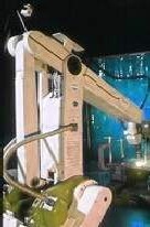
Welding can be done anywhere… outdoors or indoors, underwater and in outer space.

Nearly everything we use in our daily life is welded or made by equipment that is welded. Welders help build metal products from coffeepots to skyscrapers. They help build space vehicles and millions of other products ranging from oil drilling rigs to automobiles. In construction, welders are virtually rebuilding the world, extending subways, building bridges, and helping to improve the environment by building pollution control devices. The use of welding is practically unlimited. There is no lack of variety of the type of work that is done.

Welders are employed in many industry groups. Machinery manufacturers are responsible for agricultural, construction, and mining machinery. They are also involved in bulldozers, cranes, material handling equipment, food-processing machinery, papermaking and printing equipment, textiles, and office machinery.

The fabricated metals products compiles another group including manufacturers of pressure vessels, heat exchangers, tanks, sheet metal, prefabricated metal buildings and architectural and ornamental work. Transportation is divided into two major groups: manufacturers of transportation equipment except motor vehicles; and motor vehicles and equipment. The first includes shipbuilding, aircraft, spacecraft, and railroads. The second includes automobiles, trucks, buses, trailers, and associated equipment.

A small group of welders belongs to the group of repair services. This includes maintenance and repair on automobiles or refers to the welding performed on industrial and electrical machinery to repair worn parts.

The mining, oil extraction, and gas extraction industries form yet another group. A large portion of the work involves drilling and extracting oil and gas or mining of ores, stone, sand and gravel.

Welders are also employed in the primary metals industries to include steel mills, iron and steel foundries, smelting and refining plants. Much of this work is maintenance and repair of facilities and equipment. Another group is the electrical and electronic equipment companies. Welding done by this group runs from work on electric generators, battery chargers, to household appliances.

Public administration employs welders to perform maintenance welding that is done on utilities, bridges, government armories and bases, etc. Yet another group involves wholesale and retail establishments. These would include auto and agricultural equipment dealerships, metal service centers, and scrap yards.

Probably the smallest group of welders, but perhaps those with the biggest impact on the public are the artist and sculptors. The St. Louis Arch is possibly one of the best known. But there are many other fountains and sculptures in cities and neighborhoods around the world.

This article was excerpted from Modern Welding Technology, 4th edition, 1998, by Howard B. Cary. Published by Prentice-Hall, the book may be ordered from the Training Materials Dept., Hobart Institute of Welding Technology, 400 Trade Square East, Troy, OH 45373. http://www.welding.org

content provided by Hobart Institute Of Welding Technology

......Read More......

Thursday, February 22, 2007

Introduction : What is Welding

What are you thinking if you hear word " welding"?, hard and hazard job, hot environment, or light? Maybe it 's ten percent correct, but welding is not only that. many knowledge existed behind it, and welding engineering has given large contribution in human life. If you see vehicle on road, most of them manufactured by welding, construction of building or bridge, and all of metal joining, mostly created by welding process.

So, what's welding, according to DIN Standard 1910 Part 1, herewith definition of welding :
Welding is uniting material in welding zone by application heat and/or pressure, with or without the filler of material, e.g shielding gas, flux paste or paste, may be used to make process possible or to make it easier. The energy supplied for welding is coming from outside resources.

Welding classified into several item, based on :
- Energy transfer medium operating on the workpiece from outside sources.
- Type of Parent Material
- Physical purpose of Welding

From of them, mostly category mentioned is based on physical purpose of Welding. It is divided into two big category :

I. FUSION WELDING

  • Arc Welding
  • Gas Welding
  • Resistance Welding
  • Light Ray Welding
  • Electron Beam Welding
  • Thermomechanical Welding

II. PRESSURE WELDING

  • Diffusion Welding
  • Arc Pressure Welding
  • Resistance Welding
  • Pressure Gas Welding
  • Forge Welding
  • Friction Welding
  • Cold Pressure Welding
We will discuss one by one, please click in side bar.

......Read More......

MORE ARTICLE

ET

eXTReMe Tracker

CHK